> For the complete documentation index, see [llms.txt](https://docs.innova-drilling.com/introduction/llms.txt). Markdown versions of documentation pages are available by appending `.md` to page URLs; this page is available as [Markdown](https://docs.innova-drilling.com/introduction/innova-engineering-manual/well-seeker-x-manual/9.0-charts/9.4-travelling-cylinder-plot.md).
# 9.4 - Travelling Cylinder Plot
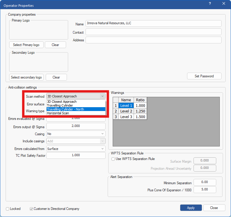
A specialised anti-collision plot that shows the relative distance and bearing of offset wells. To correctly use a TC plot, the user must have Travelling Cylinder or Travelling Cylinder North selected at operator level as the **scan method**.
* **Travelling Cylinder** if Highside (HS) is the reference.
* **Travelling Cylinder North** if North is the reference.
Note that the reference of the plot can also be changed in the Chart Properties dialog, but this does not change the reference of the scan method.
This plot requires offsets to be assigned in order to work correctly. See **section 8.2.6.4 – Select Offsets** for more information.
**TC Plot Safety Factor:** This option allows the user to apply a safety factor to the errors which are generated in the travelling cylinder plot. With a value of one entered here (default), the ellipses will generate as per normal i.e. no safety factor applied, which means touching the No-Go line on the plot effectively equates to a SF of 1. If the user enters a value of for example 1.2 here, the ellipses displayed on the TC plot will be 20% larger, 1.5 will be 50% larger etc, giving the safety factor required. **Note:** This value cannot be anything less than 1.
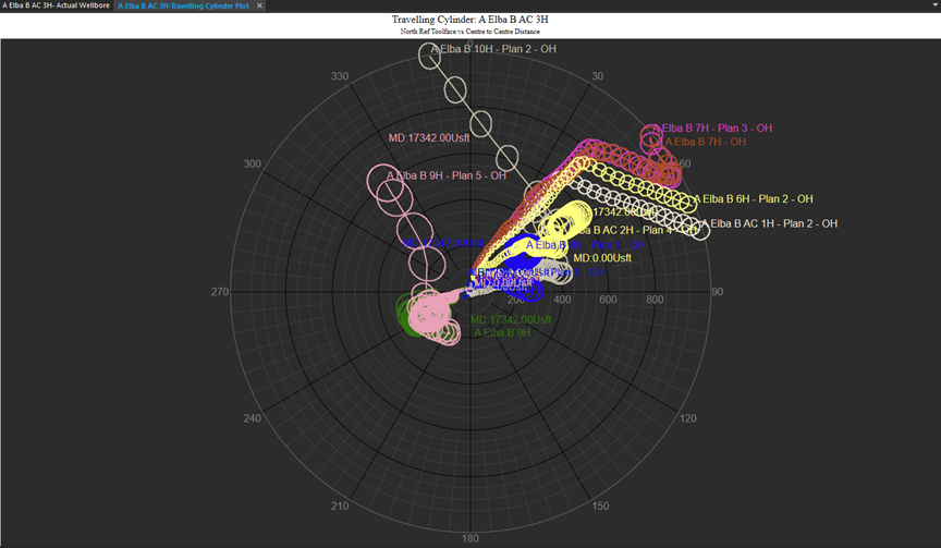
Figure 225: Travelling Cylinder Plot
The centre of the plot is the centre point of the reference well. The selected offset wells will display over the entire depth range of the individual offset wells, unless a depth filter has been applied. In the TC plot, errors are generated by adding the semi major errors from the reference and the offset and displaying this around the offset.
The user should set the reference to either north or high side in the Chart Properties, depending on the chosen scan method. The default reference can be selected in the **Anti-Collision Settings** dialog. The depth range over which the TC plot displays offset well data can be selected by the user in the Anti-Collision Settings dialog. For more information regarding the anti-collision settings dialog see **section 8.2.5.2 - Anti-Collision Settings**.
The plot can be zoomed by scrolling the mouse wheel. Double clicking brings up the chart properties.
---
# Agent Instructions
This documentation is published with GitBook. GitBook is the documentation platform designed so that both humans and AI agents can read, navigate, and reason over technical content effectively. Learn more at gitbook.com.
## Querying This Documentation
If you need additional information that is not directly available in this page, you can query the documentation by asking a question.
Perform an HTTP GET request on the following URL with the `ask` and `goal` query parameters:
```
GET https://docs.innova-drilling.com/introduction/innova-engineering-manual/well-seeker-x-manual/9.0-charts/9.4-travelling-cylinder-plot.md?ask=&goal=
```
`ask` is the immediate question: it should be specific, self-contained, and written in natural language.
`goal` is what the user is ultimately trying to achieve, the reason they need the answer. Sharing it helps GitBook give you a better, more relevant answer. A goal is most helpful when it describes the outcome the user wants rather than restating the question. For example, with `ask=how do I create an API token`, a goal like `automate deployments from our CI pipeline` lets GitBook tailor the answer to that use case.
The response will contain a direct answer to the question and relevant excerpts and sources from the documentation.
Use this mechanism when the answer is not explicitly present in the current page, you need clarification or additional context, or you want to retrieve related documentation sections.